A solid state relay - also called a solid-state relay, SSR, or a hockey puck relay - is a no-contact switching device used for a variety of electrical applications. Small and compact, solid state relays can help increase the service life of electrical applications by reducing maintenance time and costs. This article will examine solid state relays, how they work, what they are used for, and how they differ from electromagnetic relays. Plus, we will review a solid state relay wiring diagram for both DC and AC applications.
What is a Solid State Relay?
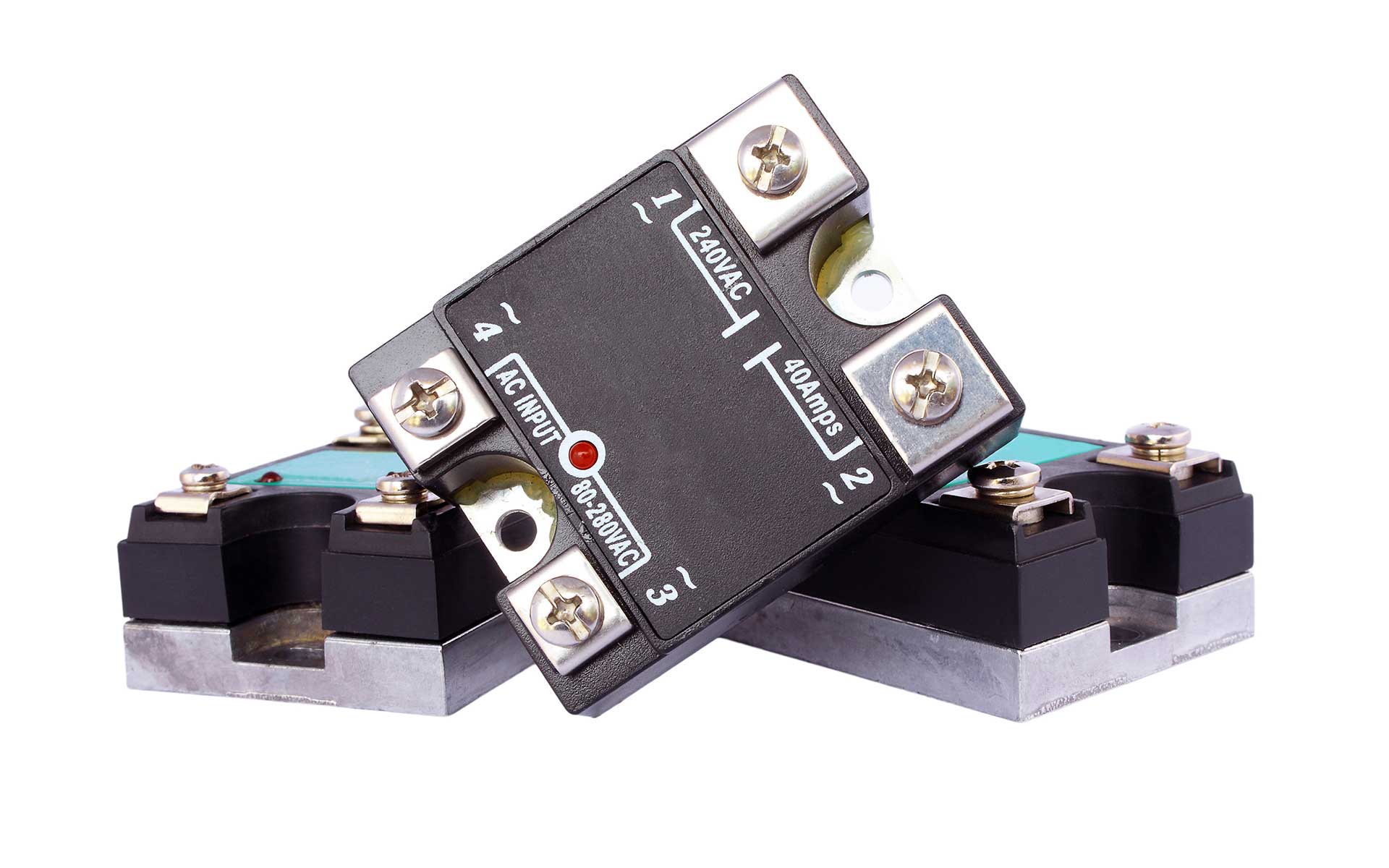
Solid state relays are electronic switching devices that switch on or off when an external voltage is applied across its control terminals. It is a non-contact switch (i.e., it can switch without contact or a spark) composed of solid-state electrical-element, which can drive high-current loads with a small control signal.
Solid state relays are widely used to perform much the same on/off and open/close functions as standard relays; however, a solid state relay switch does so without any mechanical or moving parts. Let’s examine how a solid state relay works in electronic applications to understand this significance.
How Do Solid State Relays Work?
First, let’s examine a traditional relay’s function In electrical terms. A relay is a switching device used to automatically close or open a set of contacts between two circuits triggered by an electrical input or control signal. Typically, when an electrical relay device receives no signal, the contacts are open, and the circuit is considered incomplete. However, when an electrical control signal travels to the relay terminals, the signal triggers a physical response in the relay switch, causing it to close the contacts and complete the circuit.
The same principle applies to solid state relays. However, unlike a mechanical relay, there’s no positional change of any component within the solid state relay when it switches between on/off or open/closed states. Instead, a solid state relay works by converting the incoming electrical control signal to an optical one, often output via an infrared LED or similar.
So, when the appropriate control signal encounters the input terminal of the solid state relay, the output terminal switches from OFF to ON, and when the control signal cancels or stops, the output terminal is restored to OFF. In this manner, the solid state relay provides non-contact control of the switch status of the load power supply connected to the output terminal.
What Are Solid State Relays Used For?
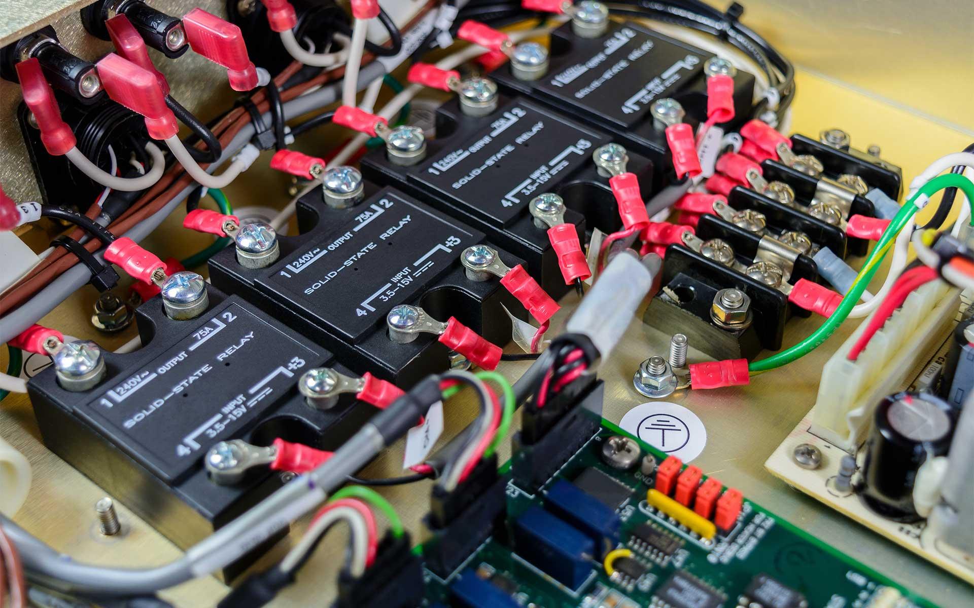
Solid state relays are regularly used in electrical applications requiring high stability, high switching speeds for high load currents, and small package size. They are used for numerous applications across many industries. Applications include industrial controls, motor control, robotics, medical equipment, instrumentation, multiplexers, data acquisition, i/o subsystems, utility meters, ic equipment, and home appliances.
Solid state relays are increasingly replacing electromagnetic relays, and a comparison of the two demonstrates why this is occurring more and more.
Solid State Relays vs Electromechanical Relays
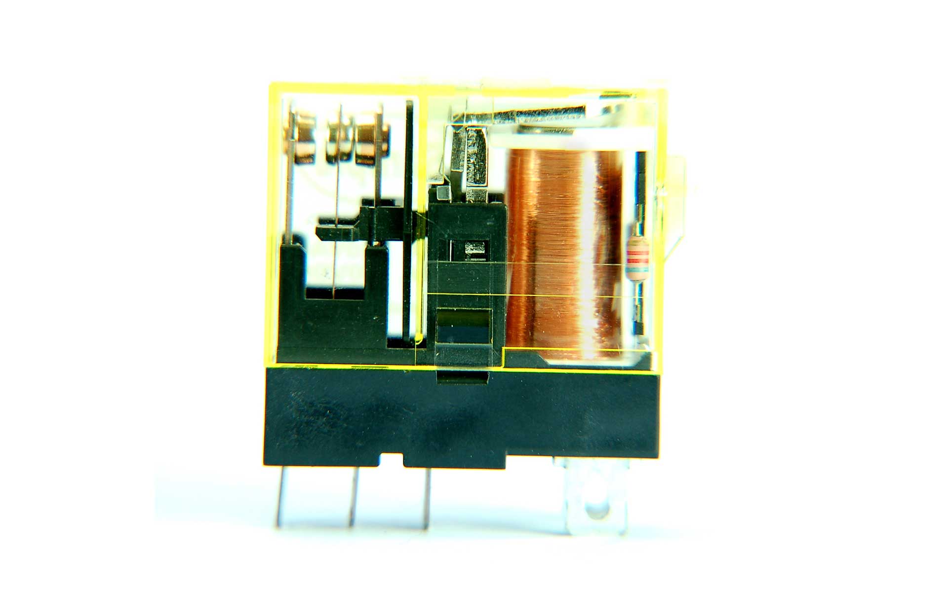
As explained earlier, solid state relays function much like electromechanical relays - with a few key differences. Electromechanical relays are switches that include three parts: the electromagnet (or coil), armature, and moveable and stationary contacts. When you switch on power to the low-voltage control circuit, the current flows through the coil, giving it magnetic properties. This magnetic force tugs on the armature, connecting the movable and stationary contacts to turn the relay ON. This process is electromechanical, hence the name.


A solid state relay is different because it has no mechanical or moving parts. Instead, it uses optical semiconductors called photocouplers to isolate input/control and output/load signals. Photocouplers change electric signals into optical signals and transmit them through space, isolating the input and output sections while transmitting the signals at high speed. Since solid state relays use electronic parts with no mechanical contacts, there are no switching contacts that can physically wear out.


There are advantages and disadvantages to each kind of relay. The benefits of electromagnetic relays are low cost, compact size, low residual voltage, no leakage current, no heat sink required, and AC/DC compatibility. However, the disadvantages are contact bounce and limited contact life, noisy action, not ideal for large currents, electromagnetic interference during operation, and the switch action cannot be fully synchronized.
The solid state relay also has multiple benefits, such as anti-vibration, anti-shock, and moisture-proof. Solid state relays also have asynchronous and synchronous switching modes, fast response times/switching power, longer life, and no mechanical moving parts or noisy action. And finally, they are compatible with digital circuits.
However, the disadvantages are leakage current, unsuitable for small output signals, provides only a single contact, the output can only be AC or DC - not compatible, and they usually need a heat sink.
Overall, the solid state relay has fewer disadvantages and more advantages when compared to electromagnetic relays. In a nutshell, solid state relays are replacing electromagnetic relays more and more across industries because the lifespan and reliability of the solid state relays are far superior to that of electromagnetic relays.
Solid State Relay Wiring Diagram
Solid state relays are typically classified according to the load power supply type, i.e., DC solid state relays (DC-SSR) or AC solid state relays (AC-SSR). In this section, we’ll review how to wire a solid state relay using a solid state relay schematic for each type of relay.
DC Solid State Relay Wiring
In this solid state relay circuit example, the DC to DC relay has four terminals and uses a DC signal to control the DC load. This diagram shows how Port 1 and Port 2 connect to the load and the DC power supply, and Port 3 and Port 4 connect to the DC control device. And that’s essentially how to wire a DC solid state relay.
AC Solid State Relay Wiring
Similarly, this AC to DC solid state relay schematic shows four terminals. However, it uses an AC signal to control the DC load. Similar to the first diagram, Port 1 and Port 2 connect to the load and the DC power supply, and Port 3 and Port 4 connect to the AC control device.
Both solid state relay circuit diagrams demonstrate the relative simplicity of wiring for AC and DC types. However, it’s essential to consult the manufacturer's specifications to confirm the relay meets the application's requirements. The product specs may also provide instructions on how to test a solid state relay, which is always helpful.
Solid state relays have gained popularity for their durability, high speed, and high-frequency switching capabilities. Peerless Electronics is authorized to carry solid-state relays from exemplary suppliers like American Zettler Inc. and Crydom. We provide industry-leading customer support and are always ready to help with questions related to products. Shop our vast, industry-leading selection of electrical products today.


