

Potentiometers, or pots, are essential components used in a wide range of industrial applications to precisely control electrical circuits. From adjusting the speed of a motor to fine-tuning the brightness of a display, these versatile components provide the necessary variable resistance to manage these and other settings. In this blog, we’re exploring everything you need to know about potentiometers, including the various types, how they function, the essentials for how to connect a potentiometer, and troubleshooting tips to ensure your potentiometer wiring works as expected.
What is a Potentiometer?
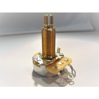
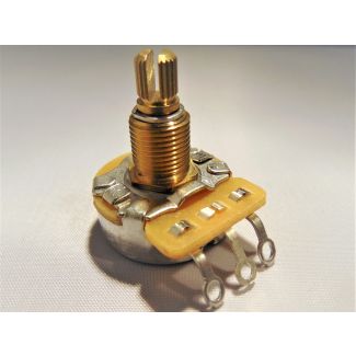
A versatile tool in electrical circuits, a potentiometer acts as a variable resistor, allowing for the adjustment of electrical current by changing the amount of resistance in a circuit. Potentiometers provide a simple and effective way to control electrical properties, such as voltage and current, across a wide range of applications, from industrial electronics to consumer devices. Potentiometers consist of three main components: a resistive element, a wiper, and three terminals or pins. Some specialized versions may have additional potentiometer pins, but the three-pin layout remains the most common.


How to Connect a Potentiometer
Determining how to connect a potentiometer is pretty straightforward once you understand its three main terminals: two end terminals and the adjustable middle terminal, which is the wiper. The following are step-by-step instructions for how to wire a potentiometer in a circuit to adjust voltage or current.
Materials Needed
Gather your potentiometer, wires for potentiometer connections, a power source (e.g., battery or power supply), and a load (e.g., LED, motor, or other component you want to control).
Step One
Begin by identifying the three terminals - Terminal 1 connects to the power supply or voltage source, Terminal 2 is the wiper in the middle, and Terminal 3 connects to the ground at the other end.
Step Two
Next, connect Terminal 1 to the power source by connecting one end of a wire to Terminal 1 (i.e., the leftmost terminal or “Vcc”) and the other end of the wire to your power source. To do this, place the pot on a flat surface with the terminals facing you.
Step Three
Connect Terminal 3 to the ground (GND) by attaching a wire to Terminal 3 (i.e., the rightmost terminal) and attach the other end of the wire to the GND of your power source.
Step Four (optional):
The wiper varies the voltage based on its position. So, you can connect Terminal 2 to the input of whatever component you wish to control, such as a motor. The voltage at this terminal will change depending on how the potentiometer is adjusted.
Adjust the Potentiometer
Once these steps are complete, turn the knob or slide the potentiometer so the wiper moves along the resistive track, altering the voltage at Terminal 2. This will allow you to control the voltage supplied to the load (e.g., adjusting motor speed).
How Potentiometers Function
A potentiometer is a type of variable resistor that adjusts resistance based on the position of its wiper, i.e., the adjustable middle terminal. In an electrical circuit, this allows for precise control of voltage and current. The wiper moves along a resistive track inside the potentiometer, altering the resistance between the wiper and the two end terminals (or potentiometer pins), which are typically connected to the power supply and ground. As the wiper shifts, the change in resistance alters the voltage at the wiper’s output. This adjustable voltage is used in various applications, such as volume control, light dimming, and motor speed regulation. Essentially, a potentiometer functions as a voltage divider, providing a variable output voltage based on the wiper’s position, enabling real-time adjustments in circuit performance.
Potentiometer Types
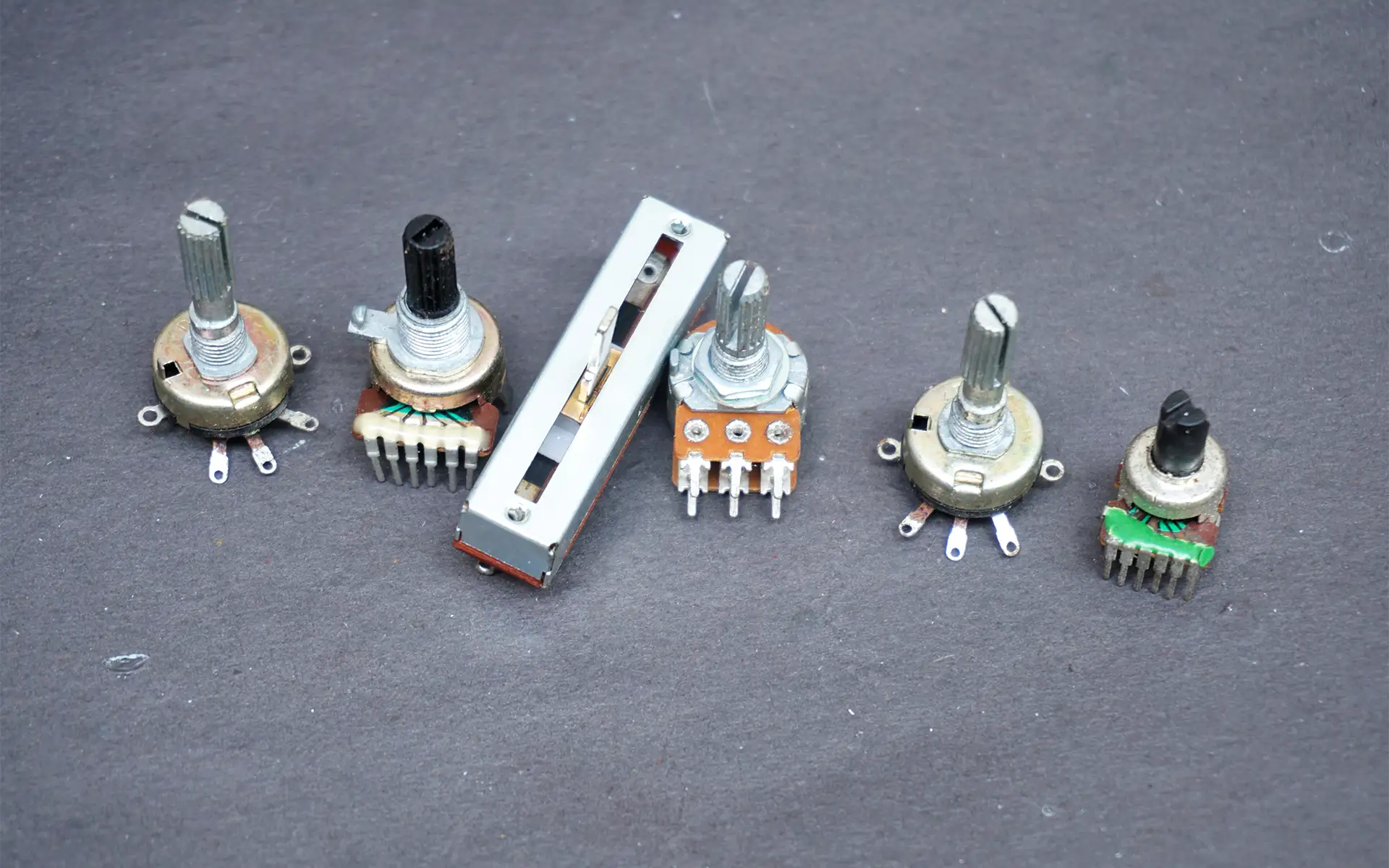
There are various types of potentiometers, each suited for different applications based on their design and functionality.
Linear
The linear potentiometer gets its name from the resistive track, which provides a direct or linear relationship between the wiper position and the output voltage. Therefore, the resistive element constantly changes in relation to the wiper position, providing precise and proportional control. Linear potentiometers are common in industrial control systems and light dimmers, where control is adjusted by sliding the shaft up or down.
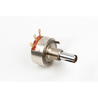
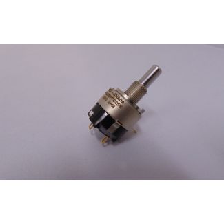
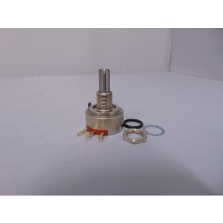
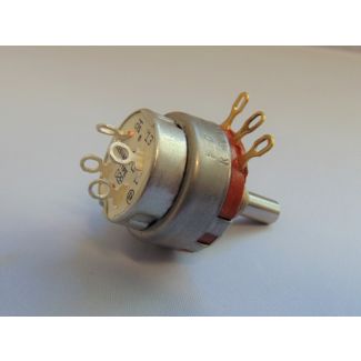
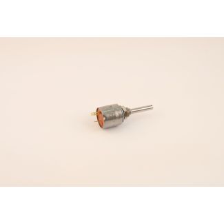
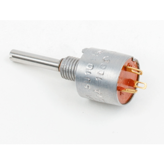
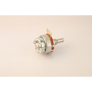
Rotary
The rotary potentiometer features a circular resistive track, with the wiper rotating around it. Depending on the level of precision needed, it is available in single-turn or multi-turn versions. These pots are common in applications such as tuning circuits in radios, musical instruments or motor speed adjustment.
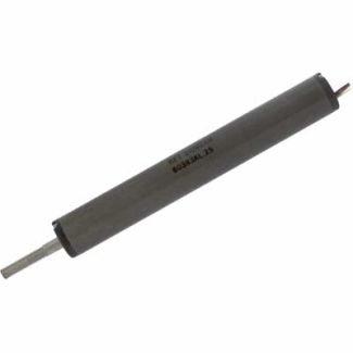
String
A string potentiometer, or draw-wire sensor, features a retractable wire attached to a spool. When the wire extends or retracts, the spool's rotation changes the resistance. String pots are ideal for measuring the position of a moving object, such as a hydraulic cylinder.
Logarithmic
With these potentiometers, the resistance curve changes logarithmically rather than linearly, meaning that smaller movements at one end of the wiper’s range result in greater resistance changes at the other end. This makes them ideal for audio applications, especially volume control, like audio and communication systems (i.e., industrial PA systems).
Rheostat
A rheostat is a type of potentiometer used specifically to adjust current flow rather than voltage. Unlike standard potentiometers, a rheostat typically has only two potentiometer connections or terminals - one connected to the resistive element and the other to the wiper. This makes it ideal for applications that require high-power dissipation, such as motor speed controllers.
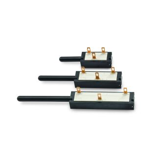
Slide
The slide potentiometer, or fader, features a straight (linear) resistive track and a wiper that moves back and forth along it. This movement of the slide changes resistance as you move along it. These potentiometers are commonly used in industrial-grade simulators to control flight parameters like throttle, pitch, or altitude adjustments.
Trimmer
The small, adjustable resistors are designed for fine-tuning and calibrating within electronic circuits, enabling adjustments to be made directly to a circuit board without any external interference from end users. Typically set once during manufacturing or servicing, these potentiometers, also called trim pots, are ideal for circuit calibration or sensor adjustments.
Potentiometer Wiring Diagram
Here is a simple diagram for a potentiometer in a voltage divider configuration. In this setup, R1 is the resistance between the power source (Vcc) and the wiper. R2 is the resistance between the wiper and the ground. The output voltage will change as you adjust the knob or shaft on the potentiometer, controlling the voltage supplied to the load.
Vcc (5V)
|
[ R1 ]
|
+----> Output (from wiper)
|
[ R2 ]
|
GND
Troubleshooting Potentiometer Wiring
If you experience functionality issues after wiring a potentiometer, several troubleshooting steps can help you diagnose and resolve common issues.
Examine for Loose Connections
Check all wiring points to ensure they are secure, especially at the terminals. Loose or poorly soldered potentiometer connections can cause erratic behavior or function failure.
Check for Shorts
A short circuit can occur if wires accidentally touch each other or if solder bridges form between the potentiometer terminals. To check for this, use a multimeter in continuity mode to test between the potentiometer pins or terminals. If there is a direct connection where there shouldn’t be, carefully rewire or resolder the potentiometer connections to eliminate any unintended shorts.
Look for Damaged Components
Physical damage or wear can affect the potentiometer’s performance, so inspect the resistive track, if accessible, for scratches, burns, or debris. For example, if the knob/shaft feels unresponsive or rough while turning/moving, then the component may need replacing.
Make Sure It’s Wired Correctly
Incorrect potentiometer wiring can cause faulty behavior. Double-check that each terminal is connected correctly: one outer terminal to Vcc (power supply), the other to GND (ground), and the middle terminal (wiper) to the circuit input/output. If the potentiometer controls voltage but works in reverse, swapping the potentiometer connections of the two outer terminals will correct the issue.
Ensure It’s Properly Grounded
A poor ground connection can cause unstable or fluctuating voltage readings. Therefore, check the ground wire to ensure it is securely attached to a reliable ground point in the circuit. Also, check to ensure metal-cased potentiometers aren’t grounded unintentionally.
Peerless Electronics: Your Online Source for Potentiometers
Potentiometers are versatile and essential components in many electrical circuits, offering precise control over voltage and current. As a full-service, authorized stocking distributor for many of today’s leading manufacturers and suppliers, Peerless Electronics provides a wide variety of high-quality potentiometers for industrial, aerospace, military, and defense applications. We also proudly hold a CMMC Level 2 Certification, ensuring the security standards required for DoD contracts are met when shopping for components with Peerless.