

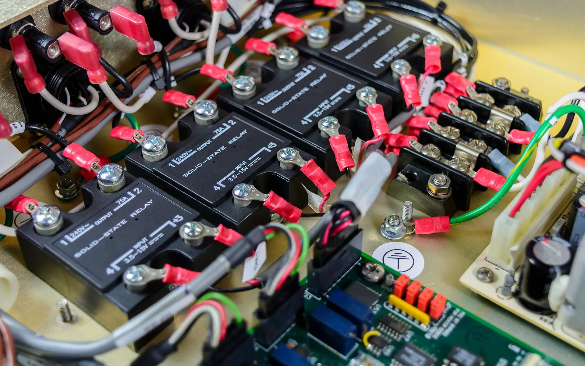
A solid state relay - also called a solid-state relay or a hockey puck relay - is a non-contact switching device designed to control electrical loads with reliability and precision. Small and compact, solid state relays can help increase the service life of applications by reducing maintenance time and costs, making them an essential component in modern electronics and automation systems.
This SSR Guide explores everything you need to know about solid state relays, including how they work, common applications, how they differ from mechanical relays, troubleshooting, and more.
What is a Solid State Relay (SSR)?
Solid state relays are electronic switching devices that turn on or off when an external voltage is applied to their control terminals. Unlike traditional mechanical relays, a solid state relay has no moving parts and operates without physical contacts or sparking. Instead, they use solid-state electronic components to control high-current loads with a low-power control signal. This contactless design makes SSRs faster, quieter, and more durable over time.
AC vs DC SSR
Depending on the specific model and intended application, a solid state relay can be designed to operate with either AC or DC input signals. Common DC input voltages include 5V, 12V, and 24V, while AC input models typically operate at standard line voltages, e.g., 120V or 240V. The input type determines how the control signal is applied to trigger the relay, so it’s important to choose an SSR compatible with the system’s control voltage.
How Does a Solid State Relay Work?
First, let’s examine a traditional relay’s function in electrical terms. A relay is a switching device that automatically closes or opens a set of contacts between two circuits, triggered by an electrical input or control signal. Typically, when an electrical relay device receives no signal, the contacts are open, and the circuit is considered incomplete. However, when an electrical control signal reaches the relay terminals, it triggers a physical response in the relay switch, causing the contacts to close and complete the circuit.
The same principle applies to a solid state relay. However, unlike mechanical relays, SSRs have no moving parts that change position when switching between on/off or open/closed states. Instead, they use electronic components to perform the switching. When an electrical control signal is applied to the input terminal, it powers an internal infrared LED inside an opto-isolator (a.k.a., a photocoupler). This LED emits light that is detected by a photosensitive receiver within the opto-isolator, activating the switching component on the output side. This process completes the circuit electronically without any physical contact or direct electrical connection between the input and output, providing safe electrical isolation.

So, when the appropriate control signal encounters the input terminal of the solid state relay, the output terminal switches from OFF to ON. When the control signal is canceled or stopped, the output terminal returns to the OFF state. In this manner, the solid state relay provides non-contact control of the switch status of the load power supply connected to the output terminal.
Solid State Relay vs Mechanical Relay
As explained earlier, solid state relays function much like electromechanical relays, with a few key differences. Electromechanical relays are switches with three primary components: the electromagnet (or coil), armature, and movable and stationary contacts. When you switch on the power to the low-voltage control circuit, the current flows through the coil, giving it magnetic properties. This magnetic force tugs on the armature, connecting the movable and stationary contacts to turn the relay ON. This process is electromechanical, hence the name.
A solid state relay differs because it has no mechanical or moving parts. Instead, it uses optical semiconductors (opto-isolators or photocouplers) to isolate input/control and output/load signals. Opto-isolators change electric signals into optical signals and transmit them through space, separating the input and output sections while transmitting the signals at high speed. Since solid state relays use electronic parts with no mechanical contacts, there are no switching contacts that can physically wear out, thereby increasing their durability and longevity.
| Feature | Solid State Relay (SSR) | Mechanical Relay (EMR) |
| Switching Speed | Very fast (microseconds to milliseconds) | Slower (5–15 milliseconds) |
| Durability (cycles) | Millions to hundreds of millions | 100k–500k typically |
| Maintenance | Minimal | Requires periodic service |
| Noise | No click, low EMI | Audible click, EMI/transients |
| Heat/Energy Loss | Continuous heat (needs cooling) | Low continuous heat, coil loss |
| Electrical Noise | Clean switching | Arcing causes EMI |
Common Applications of Solid State Relays
SSRs are widely used across various industries and applications due to their silent operation, long life, and fast switching. The following are examples of a few typical SSR applications:
Industrial Automation
SSR applications in industrial settings include control panels for machinery and process equipment, motor switching, solenoid and valve control, and heater banks with temperature control loops.
Lighting Control and Building Automation
In both commercial and residential settings, SSRs are used for automated lighting systems, motion-activated lighting, and street lighting control. Their silent operation and ability to be triggered by low-voltage control signals make them well-suited for smart building applications.
HVAC Systems
Solid state relays in HVAC systems help control compressors, blower motors, fans, and electric heating elements. Their ability to handle rapid switching without mechanical wear makes them ideal for thermostatic cycling and zone-based temperature control.
Wiring a Solid State Relay (With Diagram)
Let’s review the wiring steps using a DC control signal and an AC load as an example. Begin with the input, or control side, of the solid state relay. Connect the positive (+) control signal, such as a 24VDC output from a PLC or other controller, to the “+” input terminal of the SSR.
On the output, or load, side, connect the terminal labeled T1 (sometimes marked “load”) to one side of the AC-powered device. The T2 terminal (often labeled “line”) connects to the AC power source (line or hot). The other side of the load should wire back to the AC neutral (for single-phase applications) or to the opposite phase in a three-phase setup.

Wiring Notes to Consider
- Use a heat sink or proper mounting with thermal paste to manage the thermal load.
- Never attempt to switch both the AC line and neutral; only switch one side, typically the line.
- Use RC filters or snubber switchers if switching inductive loads (like motors).
- Always verify that the SSR type (e.g., input voltage, output type, and load ratings) matches the application requirements.
Advantages and Disadvantages of SSRs
| Advantages (Pros) | Disadvantages (Cons) |
| No moving parts – longer lifespan | Can generate heat during operation |
| Silent operation – no clicking noise | Leakage current even when "off" |
| Fast switching response time | Typically more expensive than mechanical relays |
| Resistant to shock and vibrations | Limited to specific load types and conditions |
Troubleshooting Solid State Relay Issues
Although known for their durability and reliability, solid state relays, like any electrical component, can experience problems. This can occur, for example, if the SSR isn’t installed correctly or when operated under unsuitable conditions.
A multimeter is an essential tool for testing and diagnosing SSR issues. For a basic check of the control side (input test), set the multimeter to DC voltage and apply the control voltage to the input terminals to confirm that the expected voltage is present. If not present, check the control circuits for faults. For a load side check (output test), switch the multimeter to AC or DC voltage, depending on the SSR output type. With the input activated, check the voltage across the output terminals. No voltage may indicate a failed switching component.
Common Solid State Relay Issues
Some common issues include heat build-up, incorrect wiring, or the LED not lighting up. Let’s begin with heat, or when the relay case becomes warm or hot, and the relay begins to fail intermittently. SSRs dissipate heat, especially when switching high current, and inadequate heat sinks or ventilators can cause overheating and eventual failure. To remedy this, add a heat sink or ensure the SSR is mounted properly to a metal panel using thermal paste to help conduct heat away from the device.
If the SSR fails to activate or if the load remains stuck in the ON or OFF state, incorrect wiring may be the cause. This is common when the input or output terminals are miswired. To correct the issue, double-check the wiring diagram. For DC input SSRs, ensure correct polarity on the control terminals and verify that the load is properly connected to the output side.
When the LED light is dark, there is no visual indication of the control signal, indicating a problem. This could be due to a faulty control signal, a damaged LED, or a failed opto-isolator. To check the issue, verify the control voltage with a multimeter. If it's correct, then the SSR may be internally damaged and needs to be replaced.


Peerless Electronics: Authorized Distributor of Relays
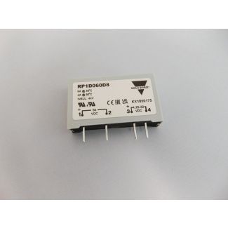
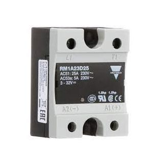
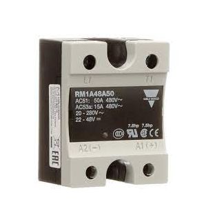
Solid state relays have gained popularity for their durability, high speed, and high-frequency switching capabilities. Peerless Electronics is authorized to carry solid state relays from trusted suppliers, including Carlo Gavazzi and Crydom. We provide industry-leading customer support, comprehensive Added Value Services, and are always ready to help with questions related to products.
FAQs
What is a solid state relay used for?
SSRs are used to switch electrical loads on and off without moving parts, commonly in industrial automation, HVAC, lighting control, and heating systems.
Can a solid state relay fail?
Yes, SSRs can fail due to overvoltage, overheating, or degradation of internal components.
Do solid state relays get hot?
Yes, they generate heat during operation, especially under heavy loads, and often require a heat sink or ventilation for thermal control.
What is the lifespan of a solid state relay?
Typically over 50 million cycles, depending on operating conditions, which is much longer than mechanical relays due to no contact wear.